Manual Image annotation
Setting up the VIA project file
Place all the images to be annotated into a single parent directory. They may be in sub-directories within this parent directory.
Before making the project file, it is necessary to produce a text file which contains the relative paths to all of the images to be annotated, one per line. It is suggested to generate this on the command line. For example, if your file structure is something like this:
annotation_project            # Parent directory
├-- via.html
├-- moth_images_november      # Images may be contained within subdirs,
│   ├-- 0001                  # and these subdirs can be arbitrarily
│   │   ├-- 100MEDIA          # nested.
│   │   │   ├-- DSCF0001.JPG
│   │   │   └--...
│   │   └-- 101MEDIA
│   │       ├-- DSCF0001.JPG
│   │       └--...
│   └-- 0002
│       ├-- 100MEDIA
│       │   ├-- DSCF0001.JPG
│       │   └--...
│       └-- 101MEDIA
│           ├-- DSCF0001.JPG
│           └--...
└-- moth_images_december
    ├-- 0001
    │   ├-- 100MEDIA
    │   │   ├-- DSCF0001.JPG
    │   │   └--...
    │   └-- 101MEDIA
    │       ├-- DSCF0001.JPG
    │       └--...
    └-- 0002
        ├-- 100MEDIA
        │   ├-- DSCF0001.JPG
        │   └--...
        └-- 101MEDIA
            ├-- DSCF0001.JPG
            └--...
Then you could generate the required file by running the following bash command from within the
annotation_projectdirectory:$ ls -1 moth_images_*/*/*/*.JPG > annotation_image_filelist.txt
Or if using fish-shell, one can easily be more flexible with regard to the exact directory structure:
> ls -1 moth_images_**.JPG > annotation_image_filelist.txt
You will then end with a file called
annotation_image_filelist.txtin theannotation_projectdirectory, which starts something like this (note the exact paths should reflect your directory structure, rather than that of this arbitrary example):annotation_project$ head annotation_image_filelist.txt moth_images_november/0001/100MEDIA/DSCF0001.JPG moth_images_november/0001/100MEDIA/DSCF0002.JPG moth_images_november/0001/100MEDIA/DSCF0003.JPG moth_images_november/0001/100MEDIA/DSCF0004.JPG moth_images_november/0001/100MEDIA/DSCF0005.JPG moth_images_november/0001/100MEDIA/DSCF0006.JPG moth_images_november/0001/100MEDIA/DSCF0007.JPG moth_images_november/0001/100MEDIA/DSCF0008.JPG moth_images_november/0001/100MEDIA/DSCF0009.JPG moth_images_november/0001/100MEDIA/DSCF0010.JPG
Note that this file contains relative paths to the images, not absolute paths. This is important for making the project portable between machines (for example if the annotation work is to be spread between multiple people). Once this file list has been generated, we are ready to set up the project in VIA.
Ensure “via.html” is placed into the parent directory containing the images to be annotated (
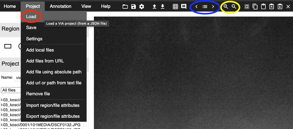
annotation_projectin the above example), then open it in you web browser by double-clicking it (you can get a copy of via.html [version 2] at https://www.robots.ox.ac.uk/~vgg/software/via/).In VIA, under “Project” in the top menu bar (see Fig. 2), select “Add url or path from text file”.
Navigate to the project directory, and select the file list we generated in step 2. The images should appear in the project pane on the left-hand side of the screen.
After checking that the image files were loaded properly, select “Save” under the “Project” menu. Leave the boxes checked, and name the project file as you wish. Your web browser will treat this as a file download. Once downloaded, you should move the project file into your annotation project directory.
Performing the annotations in VIA
Open “via.html”, ensuring it is in the parent directory containing the images to be annotated.
In the top menu, click on Project, then choose Load (see the red oval to the left in below Fig. 2). Find your VIA project file, and click Open.
If it is the first time that you work on the file, simply start with the first image. If you have already worked on the project file before and you have a saved version, scroll down to the last image that you were working on and click on it. You can now start working from that image.
You move between images (backwards and forwards) with the sideways arrows in the top menu (see the blue oval to the right in Fig. 2), or you can use the sideways arrows on your keyboard.
To zoom in and out, use the magnifying glass (+ or -, see the yellow oval in the upper right corner in Fig. 2).
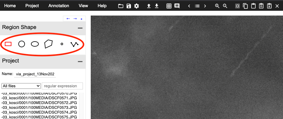
To the left, you can find different Region shapes (see the red oval in Fig. 3). The only ones I have been using are the “Circular region shape”, the “Point region shape”, and the “Polyline region shape”.
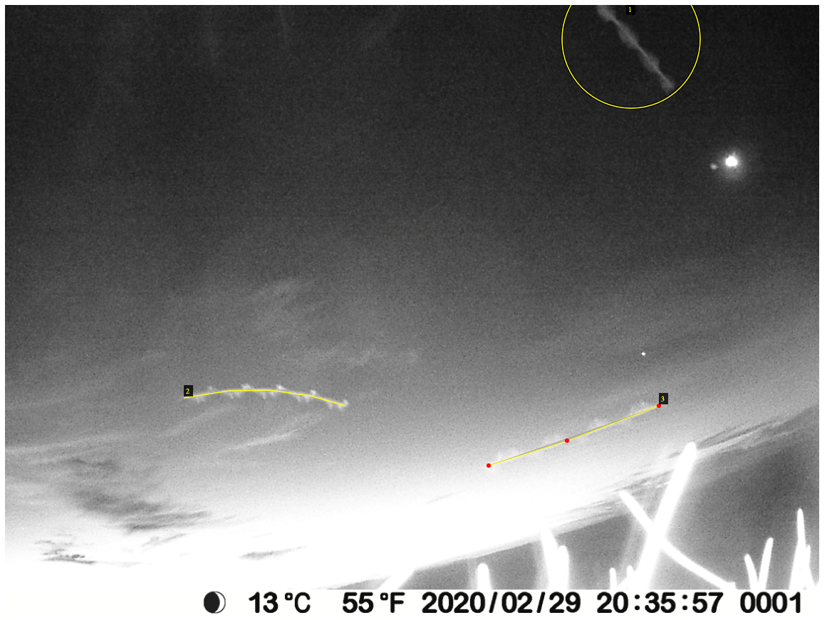
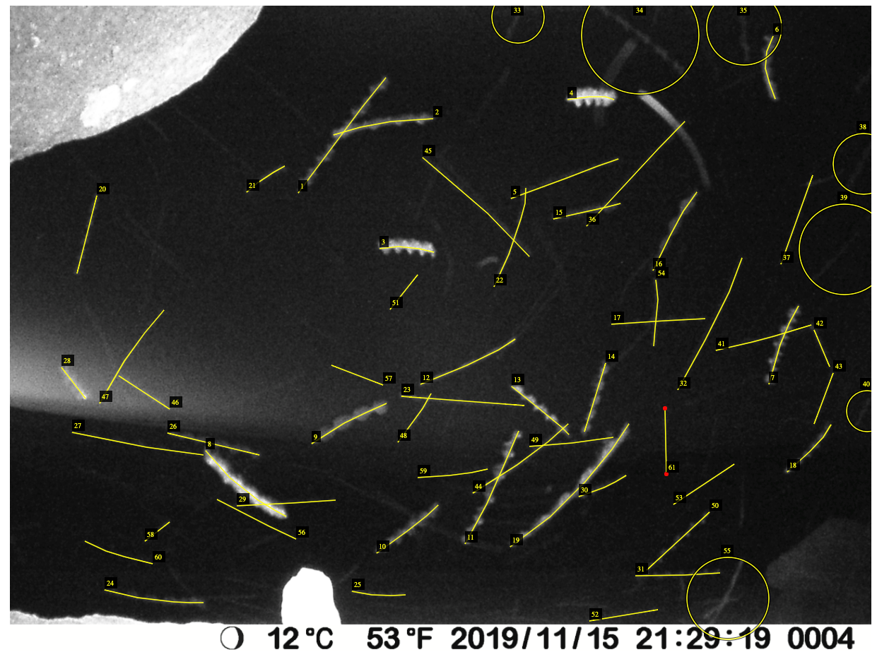
Circular region shape: This shape can be used when you cannot see the whole moth (or the whole motion blur), e.g., when the moth is going out the edge of the image (see the moth in the upper right corner in Fig. 4), if another moth or object is covering it, or if you find it hard to see where the motion blur starts and ends. To draw a circle region, simply press single click and drag the mouse.
Point region shape: This shape can be used when the moth is visible as a point (usually in brighter conditions; see the two moths in Fig. 5). There is not as much motion blur, because the sun has not set yet, meaning the camera used a shorter exposure time. It can also be used when the area of the moth is too small for the circular region shape to function. When this is the case, an error message will show up at the bottom of the screen. To define a point, press single click.
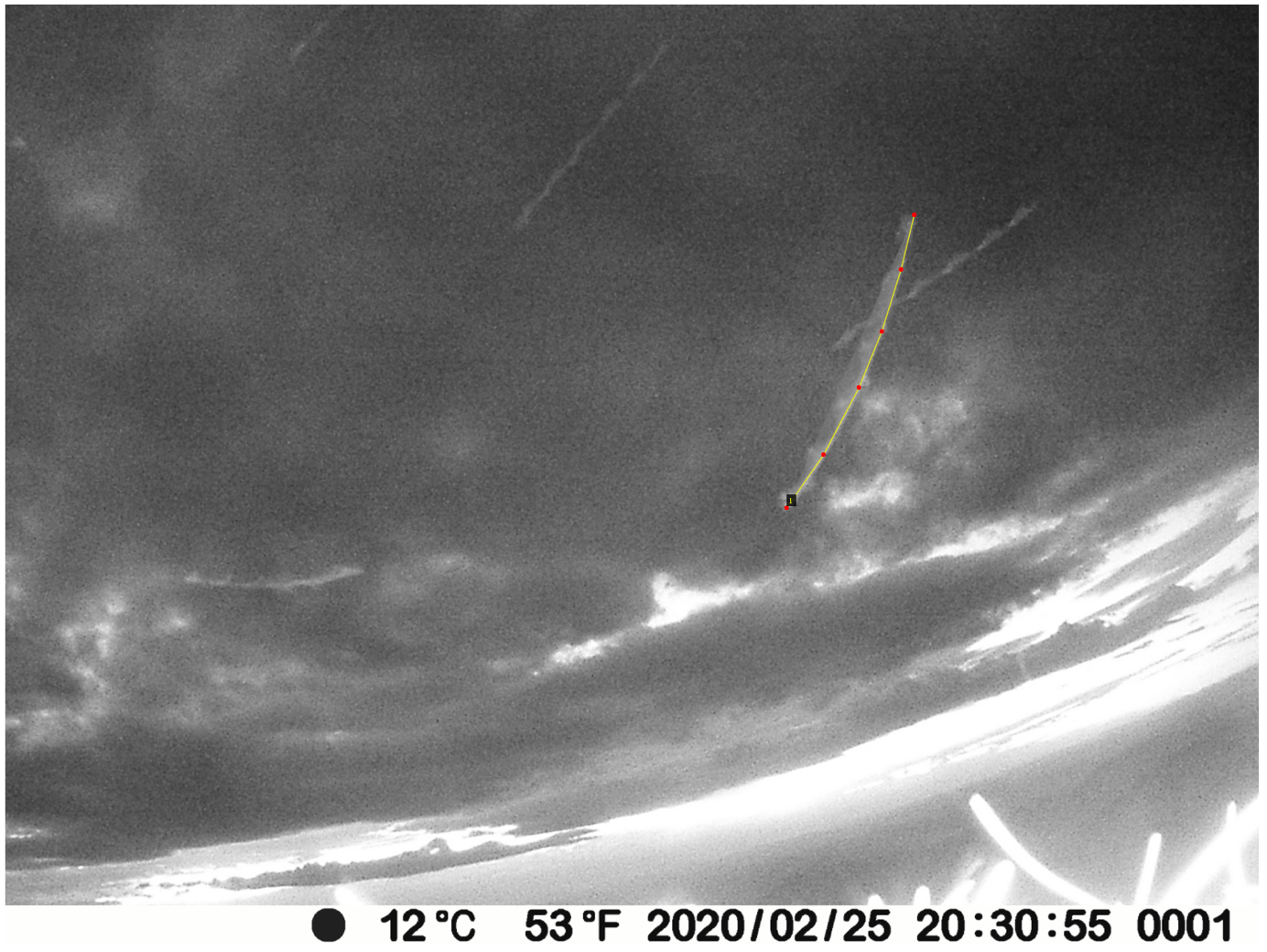
Polyline region shape: This shape should be used when the moth is visible as a line (due to motion blur). Often, you can see the flapping of the wings (see Fig. 4). To draw a polyline, single click on the start of the motion blur, and then at the end of the motion blur. To finish drawing the polyline, press “Enter” on the keyboard. It is important to make sure that the ends of the polyline annotations match up with the ends of the motion blur. Also important is to follow the line carefully - by clicking along the line several times - so that a bend is properly annotated (see the polyline in Fig. 6).
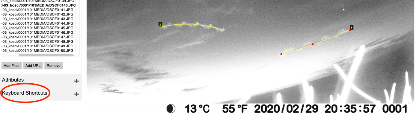
In the bottom left corner, you can find different Keyboard Shortcuts (see Fig. 7). There is an explanation to the right of each shortcut. Some of them can be quite helpful, e.g. how to “Delete selected regions”. You basically just click on the region shape and it becomes selected. Then you can delete it by clicking on the letter “d”. Some shapes can be harder than others to delete, e.g. polylines, simply because the lines are so thin. Just be patient, it will work eventually.
Do not forget to save. Do this regularly, about every 30 min. You can find “Save” in the top menu under “Project” (see Fig. 2). It is recommended to save each time to a new file, with a file name based on which image in the project you are up to. This will mitigate the risk of file corruption problems and will aid in keeping track of progress.
Examples of problematic images and FAQ
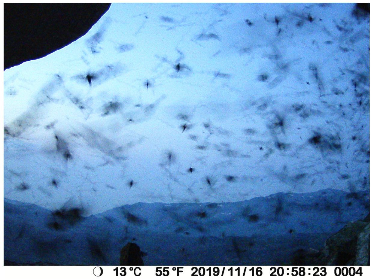
Q: What to do when an image is extremely busy and it is difficult to tell moths apart (Fig. 8)?
A: Make a note of it and do not spend too long trying to get it exactly right. Make some judgement calls.
Q: In this image (Fig. 9), there are faint moths in the background, but it is hard to see exactly where the image blur starts and ends. What to do?
A: The main thing is to be as consistent across images as possible. If you are not confident about the start and end point you could use a circle annotation (then it will be included in the abundance analysis, but not the wingbeat analysis).
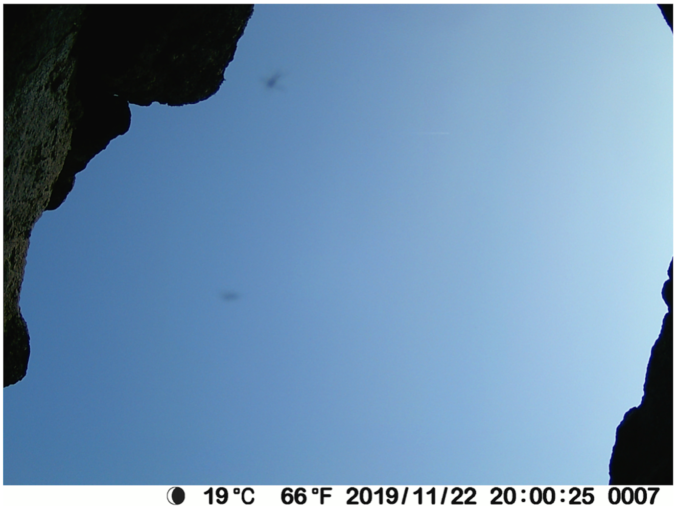
Q: In this image (Fig. 10), the flapping of the wings is not very obvious for some of the moths in the background. Should I track them anyway?
A: It is a bit of a judgement call. Ideally, we mark all moths and only moths. Obviously, this can be a bit tricky. Many of the smooth streaks might be other insects, spider web, or even rain. If you are not sure, mark it, and make a note of which image it is in. If it looks really different from other moths in the image, do not mark it. These instructions are a bit vague, but try to be consistent. Some of the moths just has lower contrast against the sky, which makes the flapping harder to see. If you zoom in, you might see it better. You could also compare the speed (based on the length of the streak) of the moth to other moths in the image.
Loading the image metadata into the VIA project file
Note: It is recommended to only perform this steps after the annotation has been completed. This is because including the image metadata in the VIA project file increases the size of the file substantially, and since it is recommended to save all incremental versions of the project file, this could become cumbersome if the metadata is included from the start.
See example notebook Flying insect activity-levels analysis.